Kawasaki FB460VBS05 4 Stroke Engine FB460V Parts Diagram for Fuel Pump
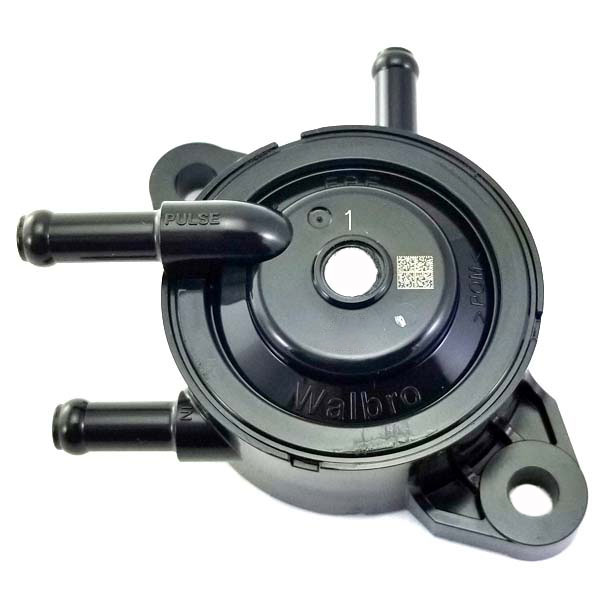
Racing Cams and Parts Walbro Pulse Fuel Pump FPC1 DynoCams
Pulse width modulation is vastly different. Instead of being constantly powered at 100% duty cycle, PWM fuel pumps have a varying fuel pressure due to controlled electrical operation. With the ignition key on, full system voltage is supplied to the fuel pump. A module, either the engine control module or a PWM module, determines the desired.
Walbro Impulse Pump WIP121 Parts Diagram for WIP121 PARTS LIST
How to easily check the function of an impulse fuel pump. I forgot to state that obviously you should make sure you have plenty of fuel in the tank. (we've a.

Best Vacuum Pulse Fuel Pump Home Appliances
I installed a pulse fuel pump on my 6.5HP Briggs & Stratton small engine. No more refueling & longer run times. Must have external fuel tank.#briggs&stratto.

Best Vacuum Pulse Fuel Pump Home Appliances
jeremy fountainthemowermedic1mail and business inquires [email protected]://www.youtube.com/themowermedic1https://www.facebook.com/themowermed.
Kawasaki FB460VBS05 4 Stroke Engine FB460V Parts Diagram for Fuel Pump
The major shift happened when fuel pumps began to be controlled with pulse-width module voltage. The fuel pump is driven by a signal that changes the power to control the speed of the motor and pressure delivered to the fuel rail during the duty cycle. The duty cycle is the measured period of time it takes for a signal to complete an on-and-off.
Pulse Width Modulated Fuel Pumps What You Need to Know About Their
Eric from OMBWarehouse.com explains how to install a fuel pump on virtually any small engine, as well as drilling a pulse fitting into your valve cover.https.

Pulse Fuel Pump Diagram
The PressureWorx PWM Fuel Module Control System, in manifold referenced fuel pressure mode, uses the engine Manifold Absolute Pressure ( MAP) sensor signal to change the output pressure of the fuel pump accordingly. The PressureWorx system consists of the: PWM control module, GM fuel pressure sensor, Delphi-sealed wiring harnesses,
DF52136 Mikuni Pulse pump 31 LPH, Dual Outlet & 90 Degree inlet Mikunioz
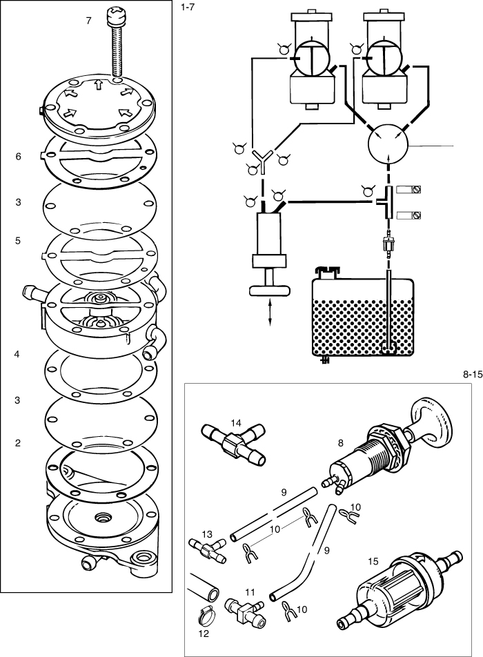
This pulse is transferred to the fuel pump by means of a pulse tube. The pulse line connects to the pulse chamber on the fuel pump. The high pressure/low pressure pulse of the crankcase pushes fuel passed a pair of one-way valves on either side of the chamber and out the outlet port. Real uncomplicated stuff, the essence of simplicity.

electric pulse fuel pump diagram
Homepage - Walbro We enable machines that make life better

(a) Incident pump pulse (solid) compared with depleted pump pulse for
A pulse fuel pump is a type of fuel pump that is commonly used in small engines like motorcycles, ATVs, and lawn mowers. In this article, we will discuss the pulse fuel pump diagram and how it works. What is a pulse fuel pump? A pulse fuel pump is a mechanical pump that uses the pressure pulses created by the engine's crankcase to pump fuel.

8558 Fuel Pump, External Pulse Marine Parts Guys
Pulse Fuel Pumps function by using an engine-supplied pressure differential that acts upon a flexible diaphragm to pump fuel. Features. Typical application: up to 25 horsepower; Suitable for 2 or 4 stroke engines; Gasoline fuel compatibility with optional levels of ethanol resistance; More Information.
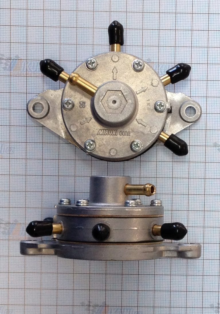
DF5292 Mikuni Fuel Pulse pump 35 LPH with Three outlets Mikunioz
20 hp B&S intek Mod.806777 type 0115-e1 with no vaccum to run fuel pump. I have changed the fuel lines, fiiter, pump and cleaned out the fuel tank. any ideal way no vaccum. When the engine has fuel it. read more

How To Diagnose An Impulse Fuel Pump YouTube
If an additional auxiliary fuel pump is used within the system it is typically placed in series with the pulse pump. You can see in the diagram, that by applying pressure to the fuel inlet chamber, the pressure from the auxiliary fuel pump can simply off seat the inlet check valve, flow into the pumping chamber, and then offset the fuel outlet

BASIC FUNCTION OF PULSE STYLE FUEL PUMPS ON JUST ABOUT ANY SMALL ENGINE
same as the pressure differential of the intake manifold. Fuel flow is also directly related to this pressure differential. So, for a given pulse fuel pump, a two-stroke engine will provide a greater pressure differential and correspondingly greater fuel flow and pressure than a four-stroke engine. Please contact Walbro for application assistance.
Diaphragm Pulse Fuel Pump Diagram
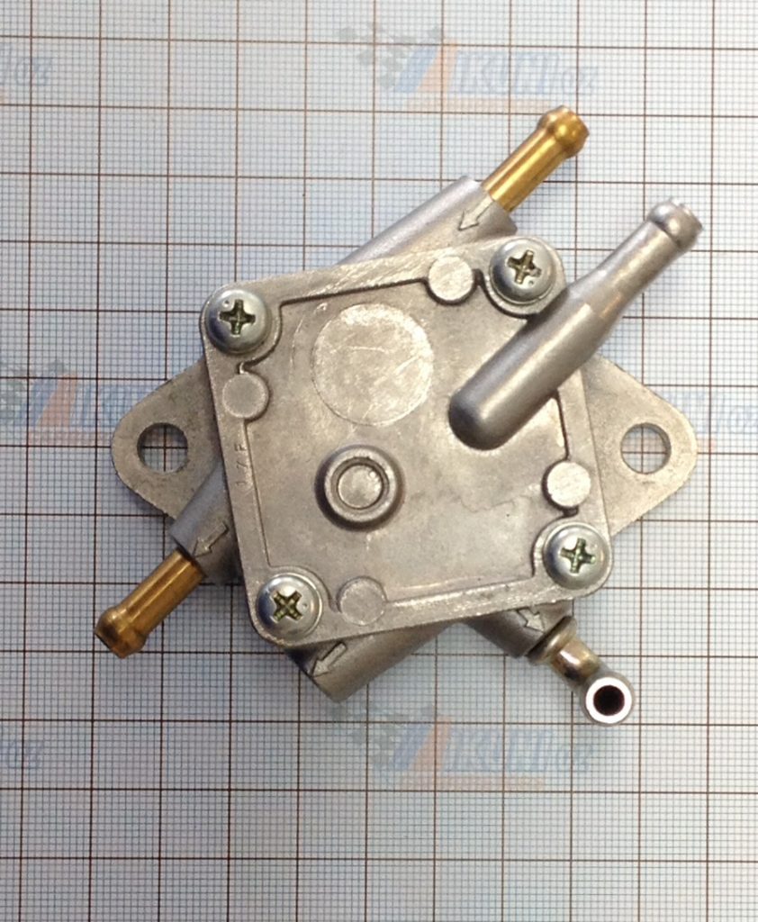
Mikuni Pulse Fuel Pump Instructions. A Mikuni pulse fuel pump is made of just a few parts. The main body is metal in three segments that form chambers inside.. Snowmobile Fuel Pump Diagram. Snowmobile fuel pumps can vary slightly. Primarily it's a difference in shape, size, and how many outlet tubes they have (1 or 2).
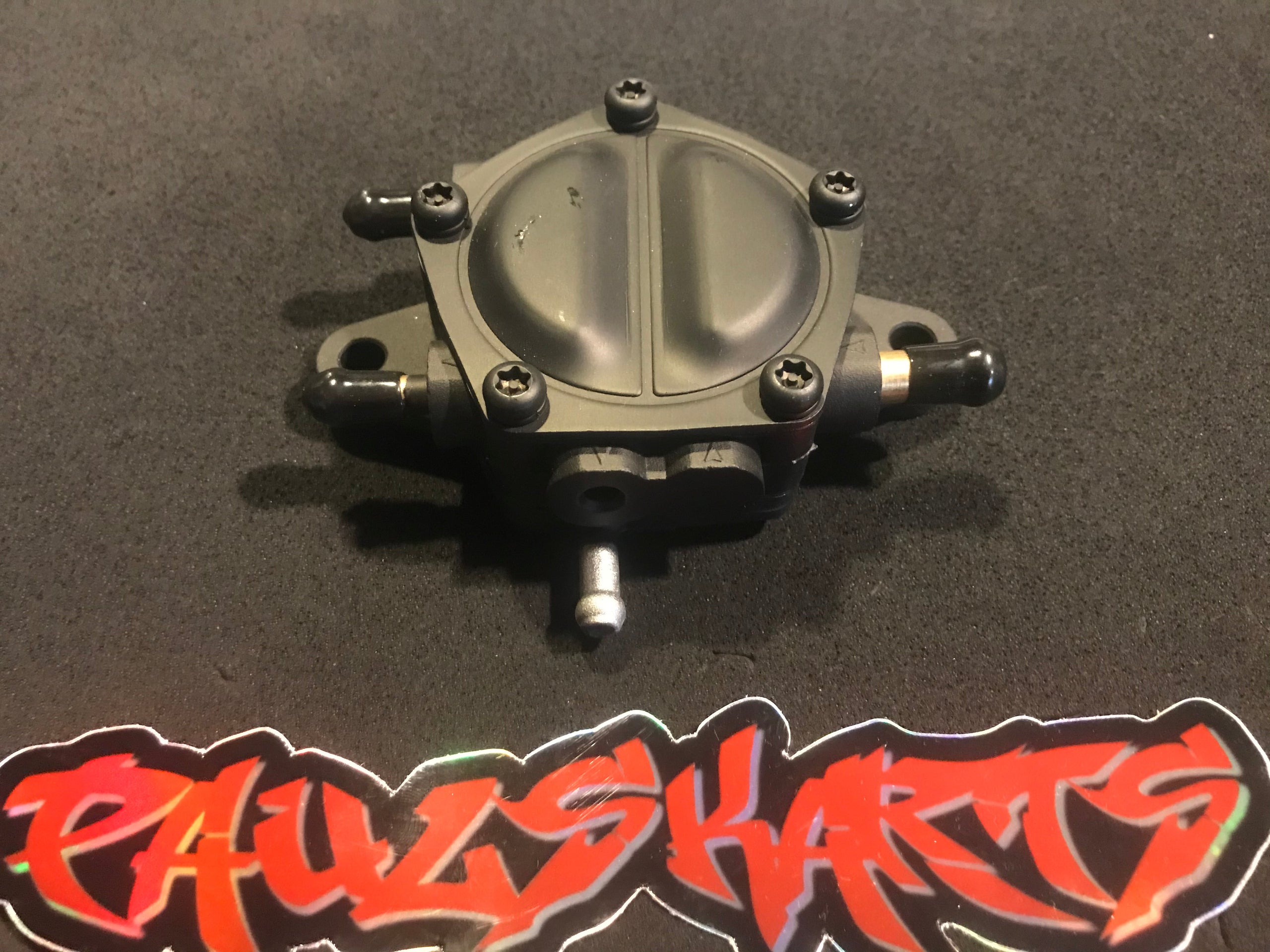
Fuel pump, pulse, 5/16” inlet, Dual 1/4” outlets, 65LPH, *most powerful
The Components. A pulse fuel pump has four tubes connected to it. One tube connects the fuel tank. Two tubes connect each carburetor and one tube connects the crankcase of the engine. When the engine revolves, the tube connecting the engine delivers fuel with a pulse of pressure at each revolution. The diaphragm pulsates with the pressure.
