[DIAGRAM] 1980 Honda Cdi Box Wiring Diagram

7 pin cdi wiring diagram LilliasKahlen
The good news is that by learning how CDI systems work and using the correct 5 pin CDI wiring diagram for your particular model, you can diagnose and fix ignition issues on your own and get your wheels back on the road. In this complete guide, you'll learn: How 5 pin CDI ignition systems work The purpose of each wire in a CDI wiring harness

250Cc 6 Pin Cdi Wiring Diagram A Comprehensive Guide WIREGRAM
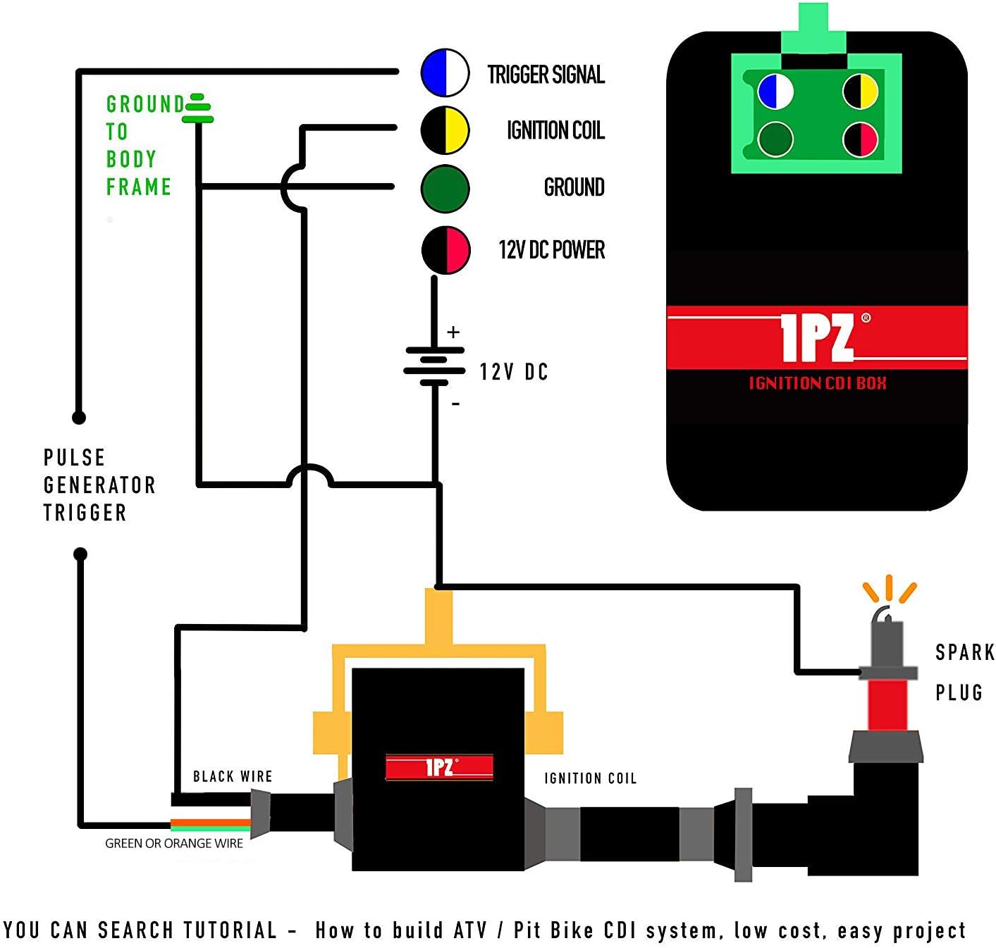
A CDI (Capacitor Discharge Ignition) Box is an essential component in the ignition system of a motorcycle or other small engine. It is responsible for providing the high voltage necessary to ignite the spark plugs and start the engine.
7 pin cdi wiring diagram LilliasKahlen
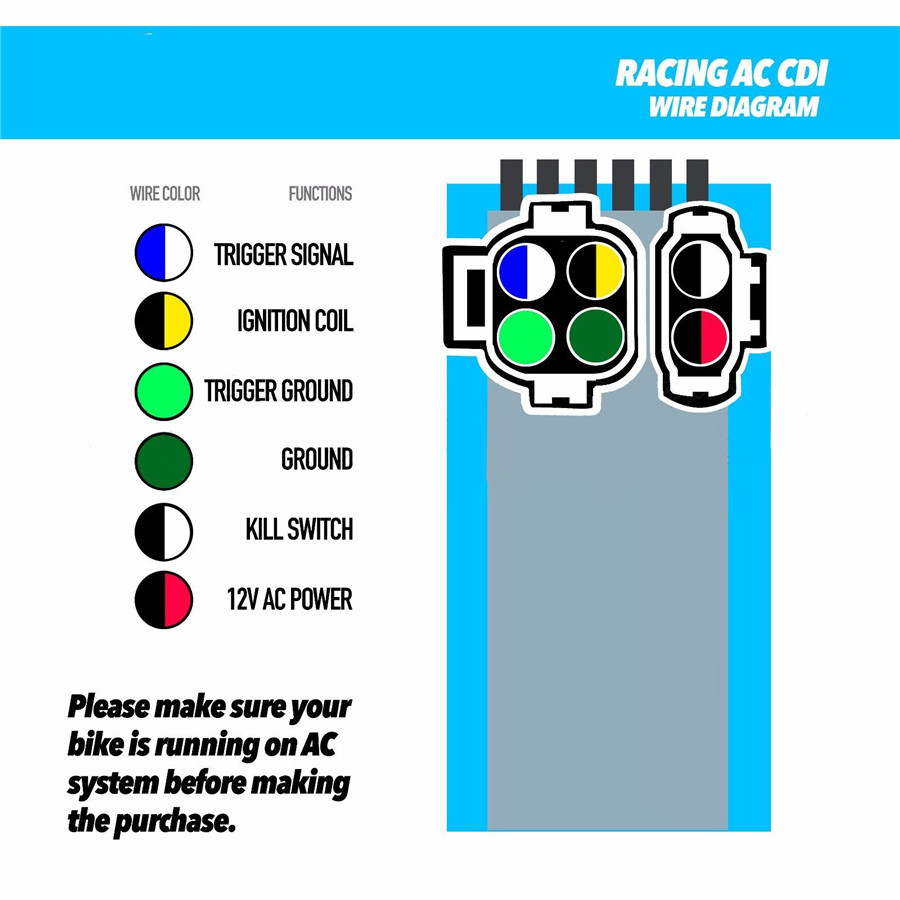
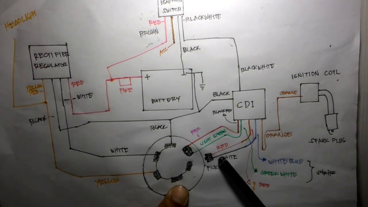
This diagram shows you exactly how to wire a 5-pin CDI. Each wire is labeled and color-coded, making it easy to identify and connect the correct wires. The diagram also includes additional information and tips to help you troubleshoot any issues you may encounter along the way.
Chinese 5 Pin Cdi Wiring Diagram Wiring Diagram
Motorcycle small engine Electrical system,original wiring diagram YAMAHA YTX 7 wire DC CDI ignition system..👈
[DIAGRAM] 1980 Honda Cdi Box Wiring Diagram
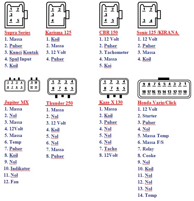
Here is another diagram of the same 5-wire CDI system and its features. On the 5-wire AC powered system the scooter is shut off by grounding out the CDI when the. Below is the pin out of the 7-wire R/R and the 11 coil stator with wiring diagram: DC 4 wire + 1 wire or 3 wire + 1 wire.

Cdi Wiring Diagram Honda Collection
CDI - 7 Wire - 3 Plug - 250cc-300cc Engine - Version 22 VMC Chinese Parts $ 37.24. Sold Out. CDI - 8 Pin - 150cc Lifan Scooter Dirt Bike - Version 52 VMC Chinese Parts $ 26.35. Add to Cart.. CDI Jumper Wire 6-Pin Honda Style CDI to 6-Pin (4+2) CDI Chinese VMC Chinese Parts $ 9.95. Sold Out.
Read Online Atv 6 Pin Cdi Diagram
The seven wire CDI box wiring diagram is an invaluable tool for any car enthusiast. The wiring diagram helps identify the electrical problem quickly and easily, so the issue can be addressed with precision and accuracy. With the help of the wiring diagram, the necessary repairs can be made before the issue becomes costly, time-consuming, and.
6 Pin Ac Cdi Wiring Diagram
mio soulty 2021 model,7 pin DC CDI ignition system,Wirin diagram tutorial,,, please follow my FB page MECHANIC DOCTOR
Cdi Ignition Wiring Diagram
VIII. Conclusion CDI System A Capacitor Discharge System, commonly referred to as CDI, is an electronic ignition device used in a number of different vehicles powered by smaller engines including ATVs, UTVs, Go-Karts, motorcycles, dirt bikes, scooters and lawnmowers.

5 Pin Cdi Wiring Diagram Color Code
7 Pin Cdi Wiring Diagram, 7 Wire Cdi Diagram - Wiring Diagram Networks 7 Pin Cdi Wiring Diagram, 21 Beautiful 7 Pin Winch Switch Wiring Diagram. Tips and tricks for reading wiring diagrams. Put a blank sheet of paper next to the wiring diagram and just draw the simple circuit. All complicated wiring diagrams are just a series of simple.
[DIAGRAM] 7 Wire Cdi Diagram
Great Prices On Honda Wiring Diagram. Find It On eBay. But Did You Check eBay? Find Honda Wiring Diagram On eBay.

Cdi Ignition Wiring Diagram For Motorcycles Online For Sale Kye Wired
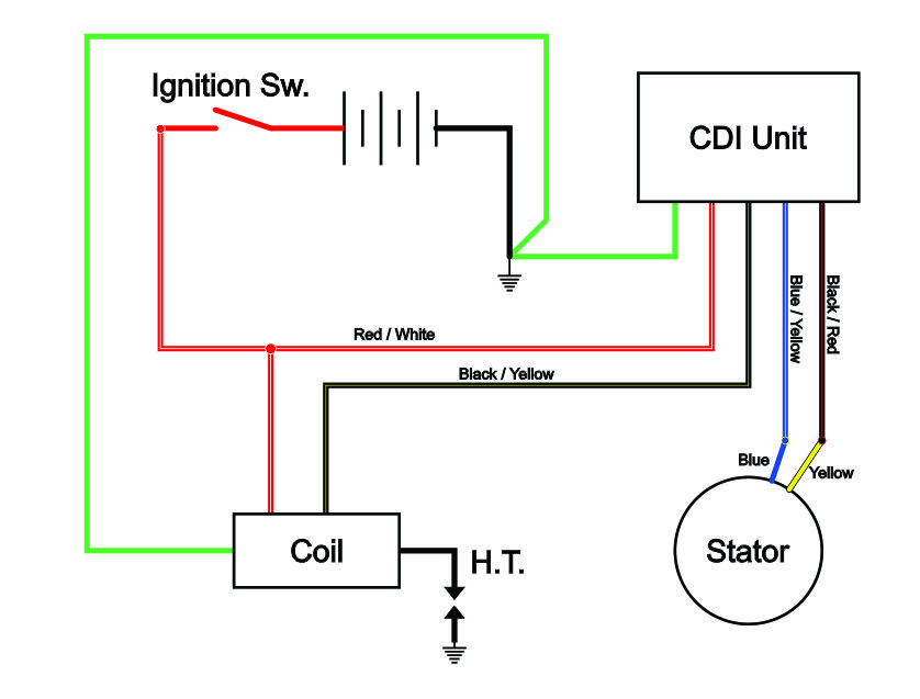
Wiring a CDI and the differance between AC/DC units.

Motorcycle Cdi Wiring Diagram
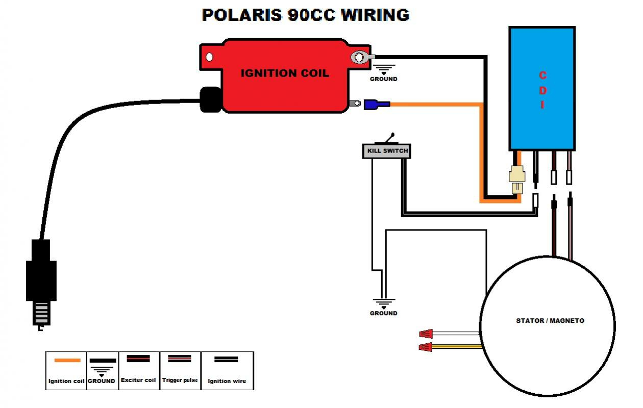
How to Test CDI Box on Polaris ATV. The steps listed below show how to test the CDI box on your Polaris ATV: Take the leads of the multimeter and link them together first. A digital multimeter should beep when used, so listen for that. Check the continuity of the ground at all of the different sites.
6 Pin Cdi Box Wiring Diagram
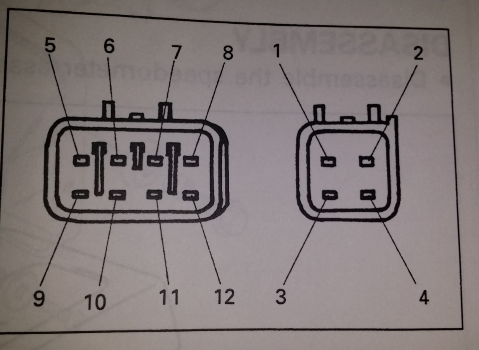
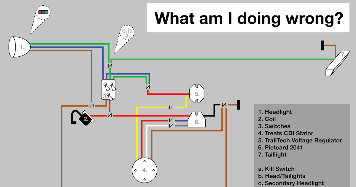
The connector block on the wiring loom from a 1998 XJ600 Diversion. There are 10 different coloured wires going into the cdi (there's 2 black and 2 of the red/white wires, so there's 12 wires going into the CDI in total): Grey. Red/white (2 x 1 red wire with white stripe, 1 white wire with a red stripe) Light blue. Yellow/black. Dark blue.
10 pin cdi wiring diagram
Once the Honda CDI box is connected, the wiring diagram will also provide details on how to properly connect the box to the vehicle's electrical system. This includes connecting it to the battery, the ground and the starter relay, among others. Additionally, different types of connectors are used when connecting the box to the vehicle's.
Gy6 Cdi Box Wiring Diagram
7- Park Light Left. 8- Reverse Light. 9- Battery ++. 10- Not Used (DIN: Trailer Battery Charging) 11- Not Used (DIN: Ground for pin 10) 12- Not Used (DIN: Coding for Coupled Trailer) 13- Ground for pin 9. NB: If you have the Reversing Aid or ParkTronic, there is a micro switch located in the vehicle side connector which deactivates the.
