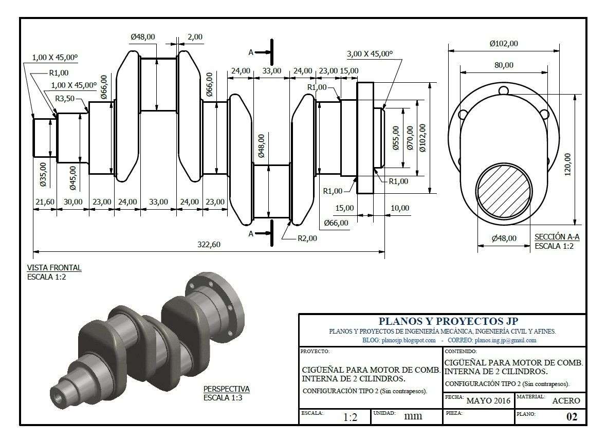
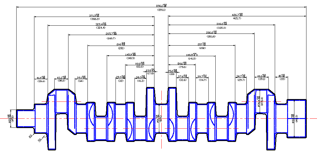
Crankshaft Drawing With Dimensions
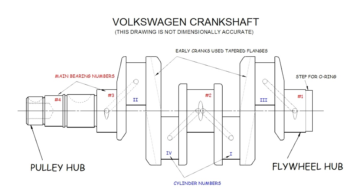
Bob Hoover's Blog Crank Basics II
I am looking for a skilled freelancer to draw a 3D crankshaft using "Inventor Auto Desk" software, based on the attached 2D drawing. The project requires a medium level of detail, with no specific materials or textures required, but it should look realistic. Although animation is not necessary, I would like the 3D model to be prepared for.

Crankshaft stock illustration. Illustration of crank, isolated 5506318
2D & 3D Best model design Of Crankshaft. The Computer-Aided Design ("CAD") files and all associated content posted to this website are created, uploaded, managed and owned by third party users.

Diesel Alfa Romeo Crankshaft 2D DWG Block for AutoCAD • Designs CAD
About Press Copyright Contact us Creators Advertise Developers Terms Privacy Policy & Safety How YouTube works Test new features NFL Sunday Ticket Press Copyright.
AUTOCAD PRACTICE crankshaft Cadbull
THE INFORMATION CONTAINED IN THIS DRAWING IS THE SOLE PROPERTY OF UNIVERSITY OF IDAHO, ME DEPARTMENT. ANY REPRODUCTION IN PART. 2-01 Crank Case 1 12,13 2-02 Sump 1 14 2-03 Case Front Cover 1 15 2-04 Front Shaft 1 16 2-05 Rear Counterweight 1 17 2-06 Crank Pin 1 18 2-07 Front Counterweight 1 19
Crankshaft CAD Files, DWG files, Plans and Details
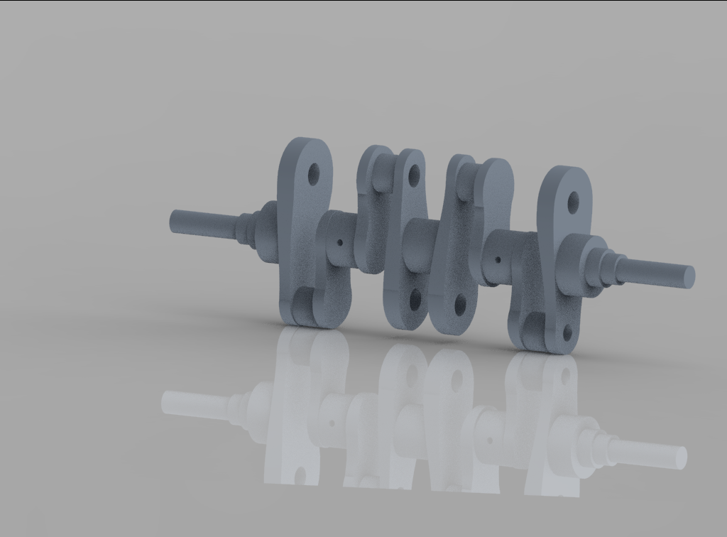
Crankshaft 2D & 3D Model. Crankshaft 2D & 3D Model. / Loading. Crankshaft Sub-Assembly. Folder. October 17th, 2017 Sealed Needle Bearing.SLDPRT. sldprt. October 17th, 2017 Crankshaft Sub Assembly.JPG. jpg. October 17th, 2017 View comments (0) Comments (0) Please.

How to Make Crank Shaft in AutoCAD YouTube
The crankshaft consists of main bearings, which are also called main journals. The crankshaft is supported by the main bearing on the main journals. A balanced load is provided in the opposite direction of the crankarm for equilibrium. A crankshaft is usually manufactured of alloy steel by casting or forging process. It is machined and grounded.
Solidworks tutorial Crankshaft YouTube
crankshaft journal and crank cheeks and near the central point Journal. The edge of main journal is high stress area. Analysis Results. So we can Say that Dynamic FEA is a good tool to reduce Costly experimental work. 7. Conclusion The crankshaft model is created by Solid workV17 software then the model created by Solid workv17 was imported to.

Crankshaft Drawing With Dimensions
Dassault Systèmes 3D ContentCentral is a free library of thousands of high quality 3D CAD models from hundreds of suppliers. Millions of users download 3D and 2D CAD files everyday.
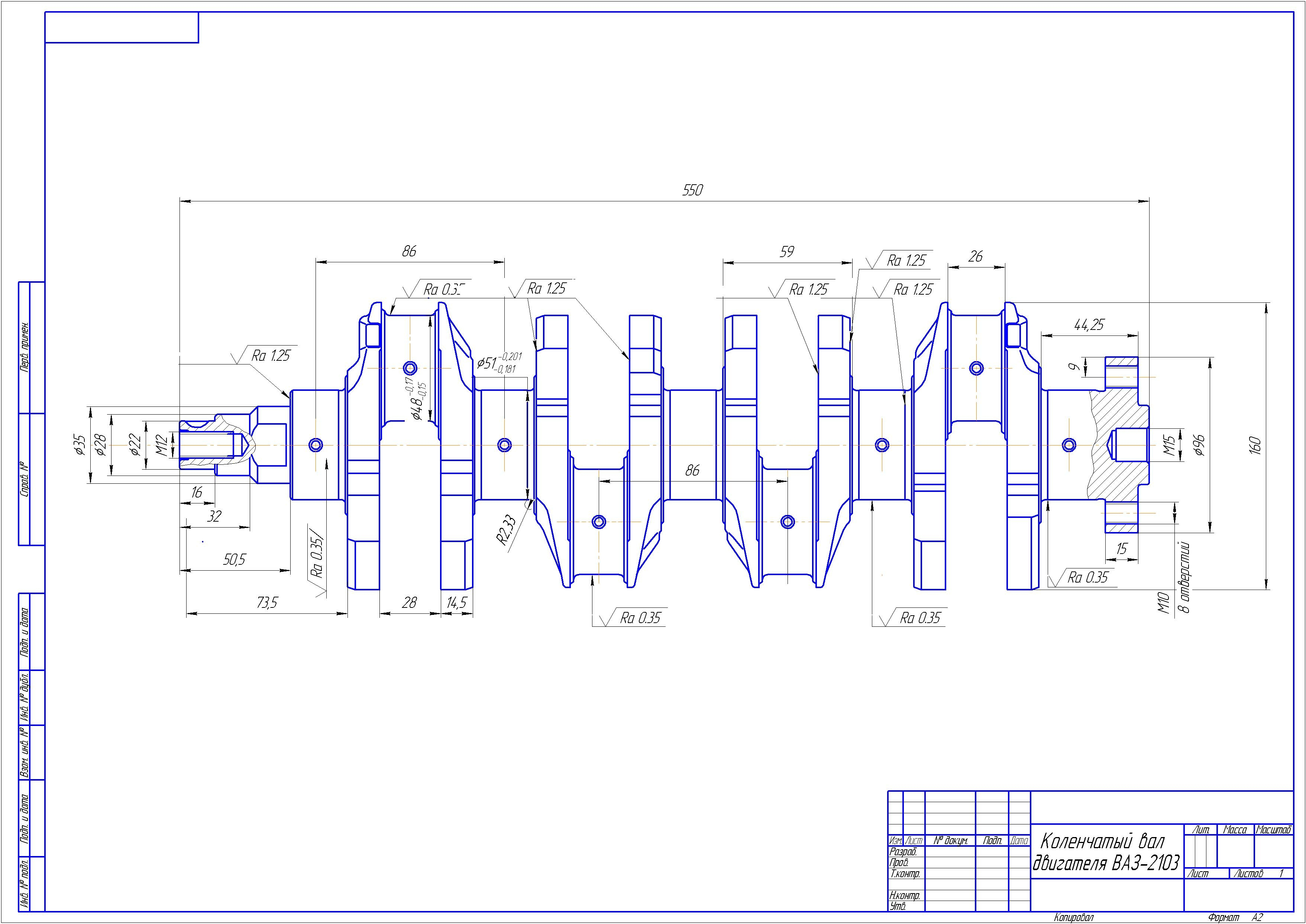
Engine crankshaft 2103 Download drawings, blueprints, Autocad blocks
The crankshaft is designed considering two positions of the crank: When Crank is at Dead center (Maximum Bending Moment). When Crank is at an angle where Twisting Moment is maximum. When Crank is at dead center. Step-wise procedure: Draw a Free Body Diagram of the Crankshaft with various horizontal and vertical forces. Calculate the piston force.
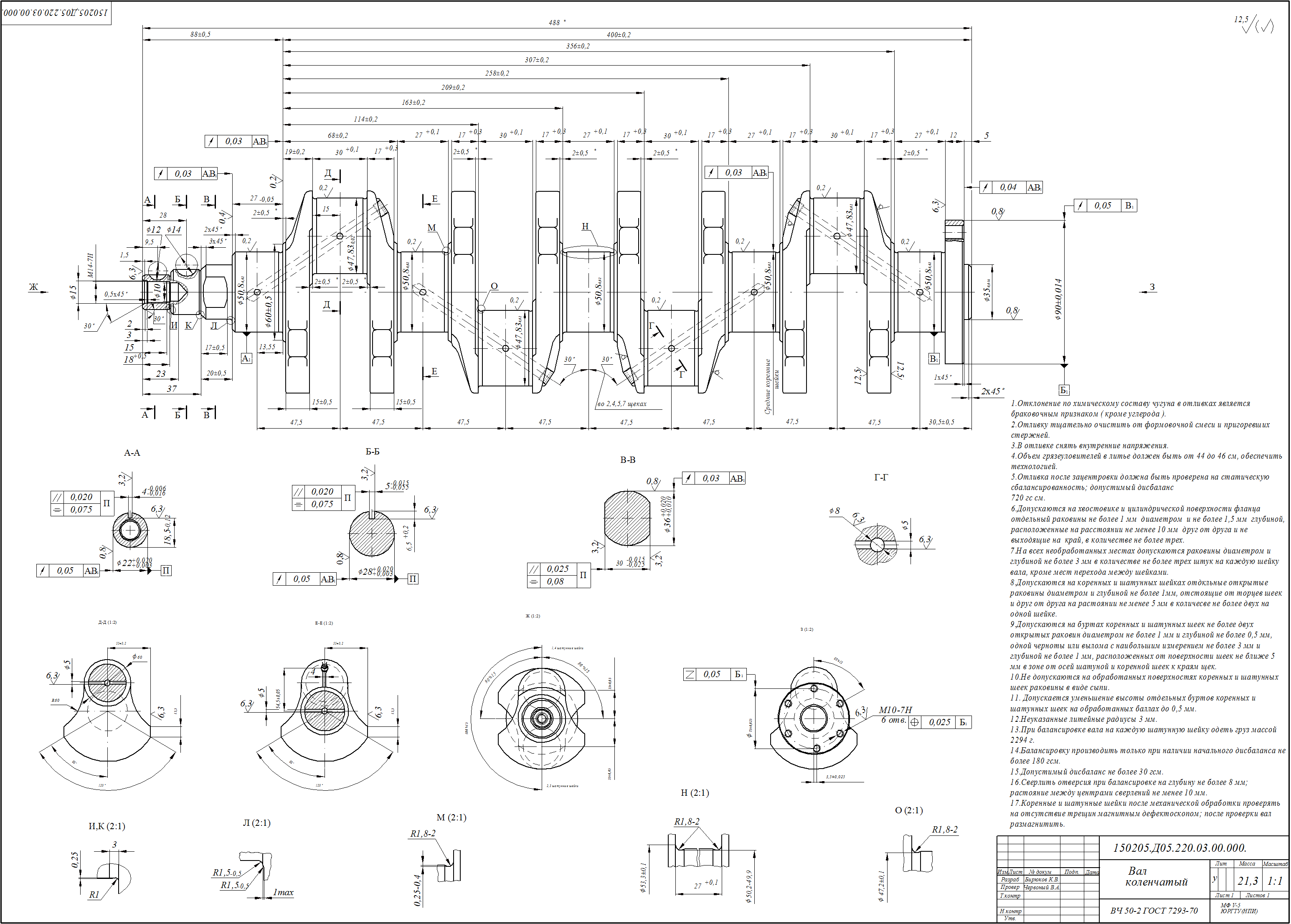
Working drawing of car crankshaft Download drawings, blueprints
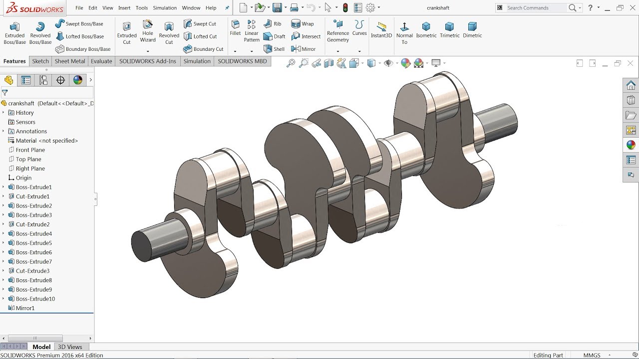
This is provide a detailed description of the geometric form of a part of an Crankshaft drawing - Solidworks Drawing Tutorial. They tend to be complex drawings that show in detail parts that may be included in minimum detail on general arrangement drawings.

How to model a Single cylinder crank shaft in simple steps? GrabCAD
AutoCAD 2D & 3D TutorialsIn this video I show you how to Make 3D Engine Crank shaft For Making Assembly of 4 stroke Engine Using Autocad Commands Shortcuts F.

V6 Engine CrankShaft SolidWorks tutorial Solidworks tutorial
Detail 2D drawing of piston and connecting rod in AutoCad. The Computer-Aided Design ("CAD") files and all associated content posted to this website are created, uploaded, managed and owned by third-party users.

Drawing old engine crankshaft assembly Royalty Free Vector
A crankshaft contains two or more centrally-located coaxial cylindrical ("main") journals and one or more offset cylindrical crankpin ("rod") journals. The two-plane V8 crankshaft pictured in Figure 1 has five main journals and four rod journals, each spaced 90° from its neigbors. Figure 1: Example (2-plane) Crankshaft

SolidWorks Tutorial Crankshaft YouTube
Free CAD and BIM blocks library - content for AutoCAD, AutoCAD LT, Revit, Inventor, Fusion 360 and other 2D and 3D CAD applications by Autodesk. CAD blocks and files can be downloaded in the formats DWG, RFA, IPT, F3D. You can exchange useful blocks and symbols with other CAD and BIM users.
Design Guide of Crankshaft
Download CAD block in DWG. Development of a piston and connecting rod design. includes: views with specifications. (112.77 KB)

SolidWorks Tutorial Crankshaft YouTube
About Press Copyright Contact us Creators Advertise Developers Terms Privacy Policy & Safety How YouTube works Test new features NFL Sunday Ticket Press Copyright.
