1W LED Driver Circuit Basic Electronics
1W LED Driver Circuit Basic Electronics
What type of circuit should I use? Is one better than the other…Series, Parallel, or Series/Parallel? The requirements of a lighting application often dictate what type of circuit can be used, but if given the choice, the most efficient way to run high power LEDs is using a series circuit with a constant current LED driver.
How to Make 1 A Constant Current LED Driver Circuit Circuit Diagram
4 Answers Sorted by: 5 You cannot directly drive 12V LEDs from arduino. If driving only one LED, use a transistor. Otherwise use a ULN2003 IC to drive multiple LEDs. Better off, order the normal LEDs. You will save area on your RC device. Here is a video that will hep you using ULN2003.
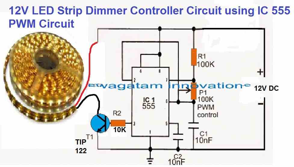
LED Strip Light Dimmer Controller Circuit Homemade Circuit Projects
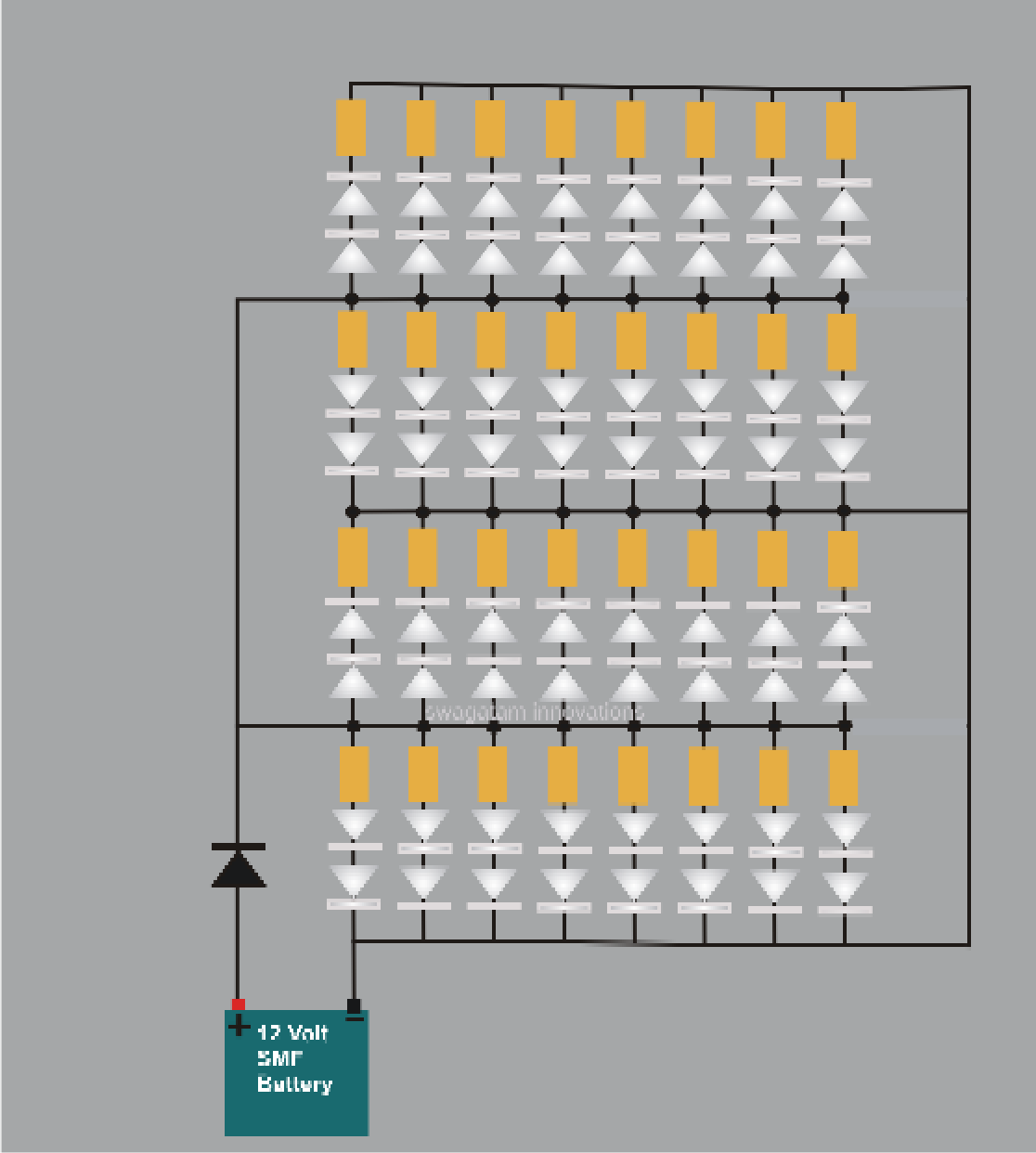
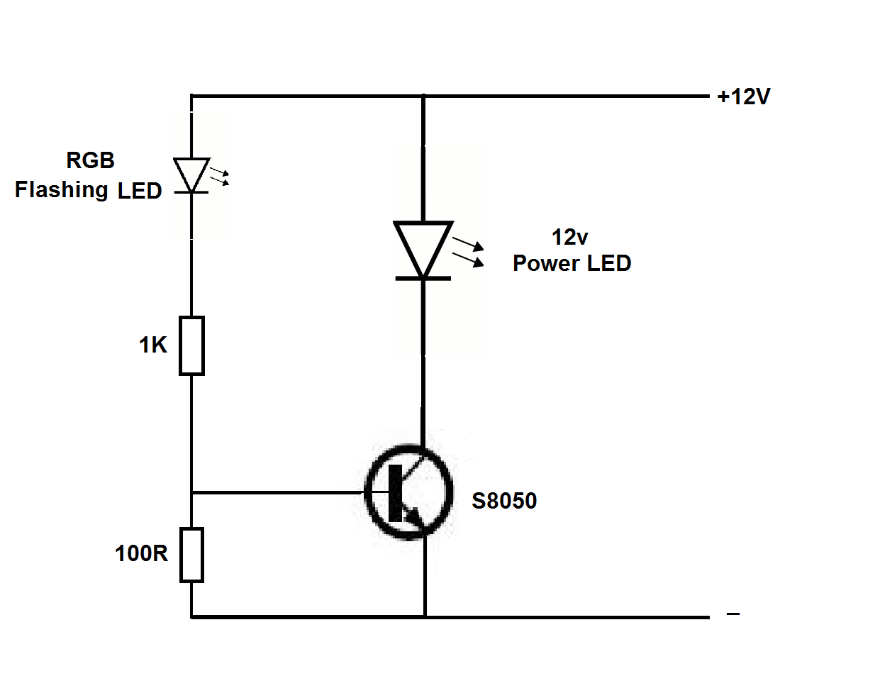
We want the forward voltage of the LEDs to match as closely as possible with the 12 V spec of the driver. Therefore we add the 3 LEDs in series, so that the total forward voltage of the LED string becomes 3.3 + 3.3 + 3.3 = 9.9 V. This is close to 12 V but still not precisely equal.
Led Driver Circuits Diagrams
Sep 14, 2021. #6. The datasheet for the IRFZ44 shows that some of them will barely turn on when the Vgs (threshold voltage) is 4V but all of them will fully turn on when Vgs is 10V. An IRLZ44 has some of them barely turned on when Vgs (threshold voltage) is 2V and all of them are almost fully turned on when Vgs is 4V.

Surge Protected Cheap Transformerless HiWatt LED Driver Homemade
How to build AC to DC 12V LED Strip Driver Circuit Circuit Digest 97.6K subscribers Subscribe Subscribed 5.2K views 2 years ago This is a very miniature version and can only be used for.
12v Led Circuit Diagram
Step 1: 3 Volt Basic LED Circuit With 10 Ohms Resistor. The above diagram shows a 3V LED circuit, in this circuit there are two AA cells are used. When you are operating an LED with 3V you have to use minimum 10 ohms resistor . For more details visit Simple Basic LED Circuit Ask Question Step 2: 6 Volt Basic LED Circuit With 390 Ohms Resistor.
led driver circuit diagram pwm Wiring Diagram
LED Driver. Driving a 12V LED strip with an N-channel power mosfet is pretty simple, but we should consider some design facts.. (R1) in my LED Driver circuit because I worried* much about the 'gate capacitance' (and switching time) of the MOSFET. One datasheet of IRLZ44N shows 1700pF typical input capacitance and 48nC total gate charge.
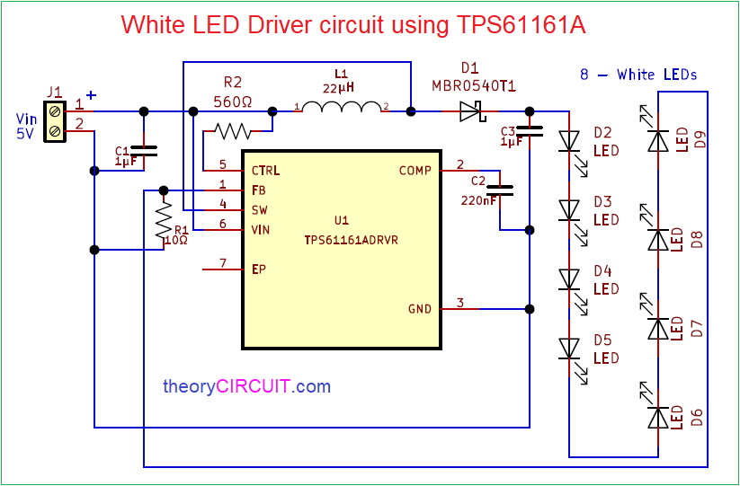
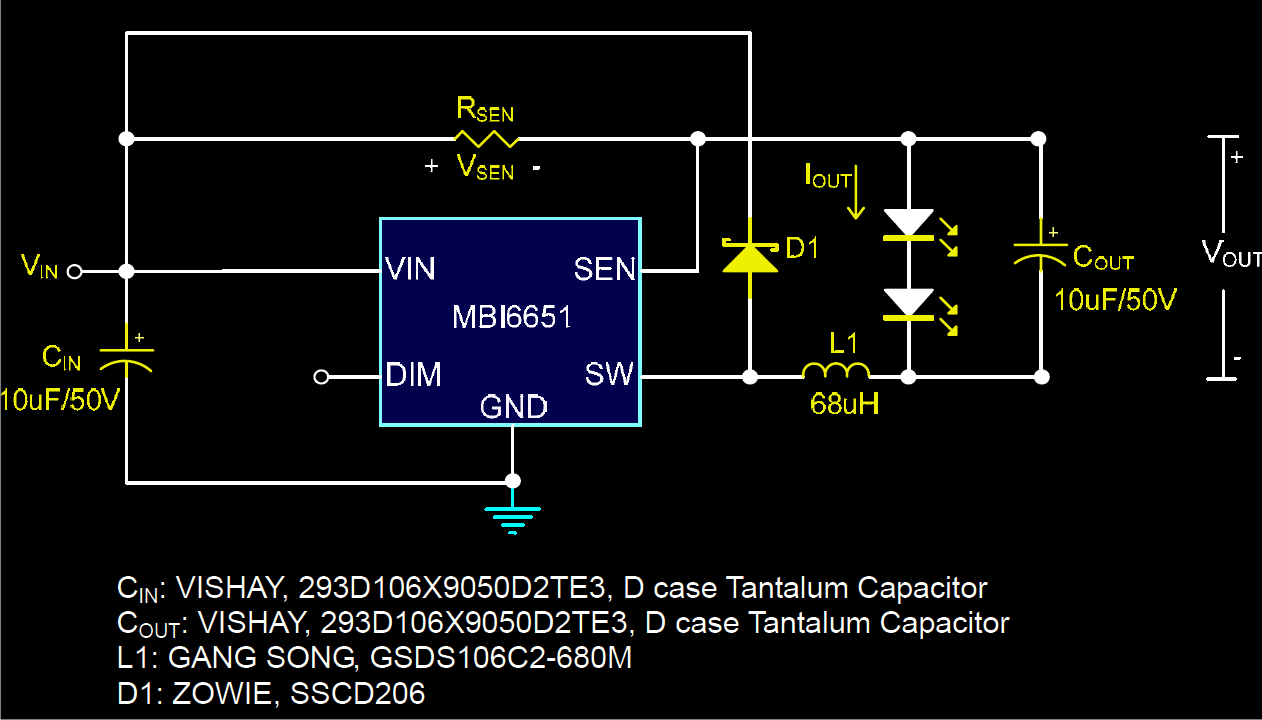
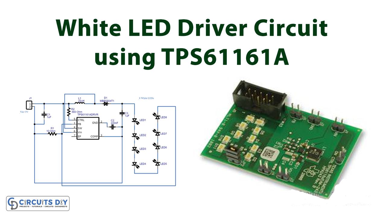
White LED Driver circuit using TPS61161A
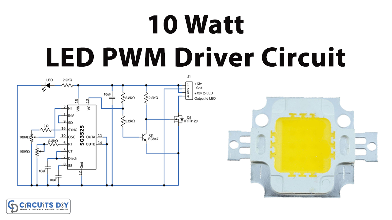
Simple 10W High Power LED Driver Circuit. This is my project for handmade flashlight when using 10W High Power LED voltage 12V DC. Indeed, by using this LED light produced is very bright. However, to use this LED requires a power of 10W and 12V stabilized voltage, so that LEDs are more durable long lasting without reducing the productivity of.
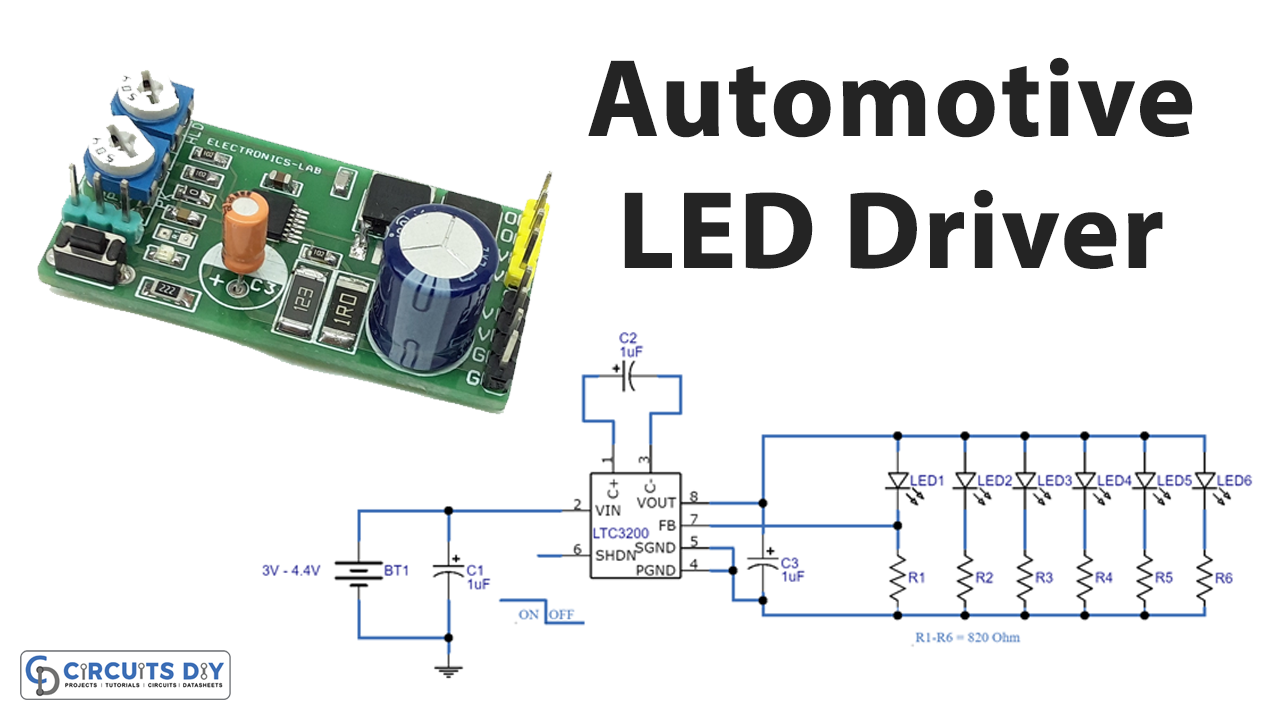
Automotive LED Driver Circuit LTC3200
Step 2: Buck LED Driver. The buck LED driver is used if the supply voltage is higher than the LEDs' combined forward voltages. For example, you may want to use a 12V source to power a single LED which requires 3.5V. This circuit is similar to that of the constant voltage source's except that this is constant current.
2 Compact 12V 2 Amp SMPS Circuit for LED Driver Homemade Circuit Projects
Figure 1. Instrument cluster dashboard indicators. The electronic circuits used to drive LEDs implement transistors. One typical circuit topology used to drive LEDs is the linear topology, in which the transistor operates in the linear region.
12v Lamp Flasher Circuit Diagram
The LED driver is a device that drives the LED voltage converter by regulating the power supply to a precise voltage current. Most times, the LED current driver consists of the following input: High voltage power frequency AC Low voltage AC High-frequency AC Low voltage DC High voltage DC
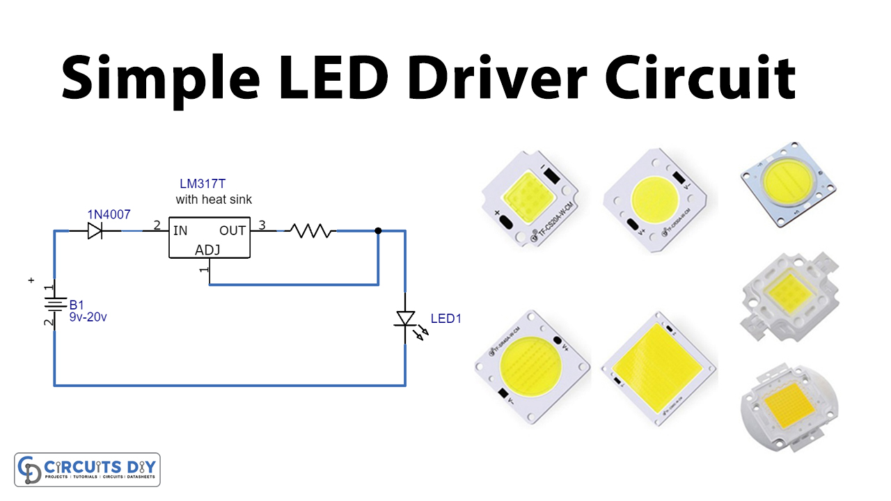
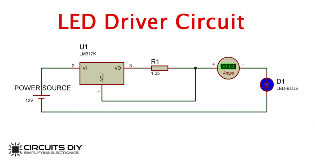
LED Driver Circuit using LM317 Voltage Regulator
What is an LED Driver? LED drivers are specialist power conversion devices used with LED equipment. What is an LED? A light-emitting diode is a small component made from an electrically conductive material. These emit light of different colours when current passes through, triggering the release of light particles called photons.
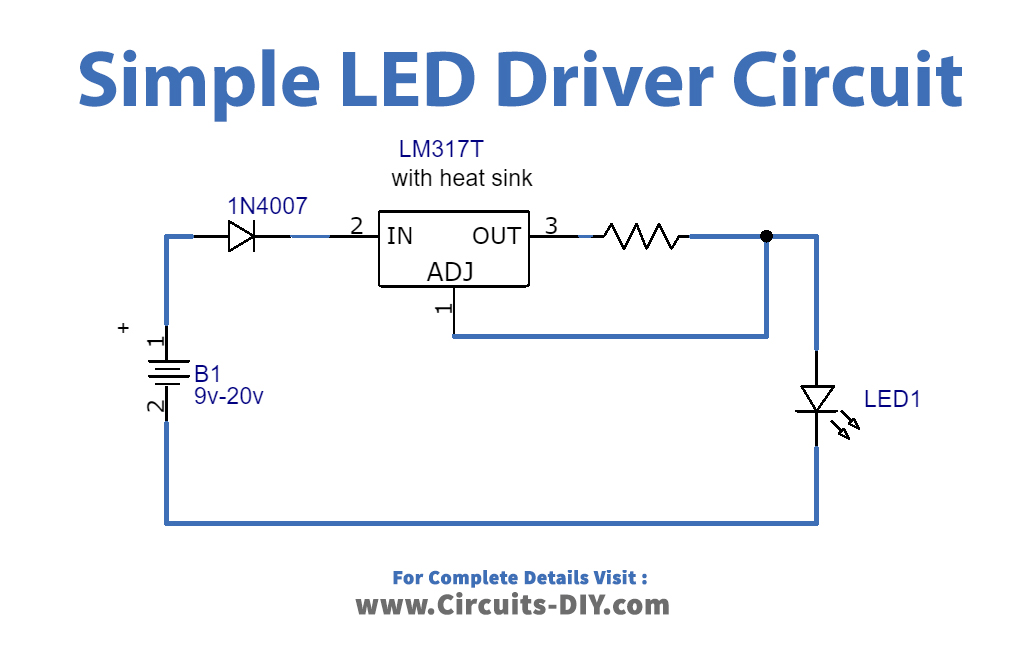
LED Driver Circuit using LM317 Voltage Regulator
SKU: EL114185 Quote Now This is a high-performance, adjustable constant current, and PWM dimmer project. It provides accurate output constant current and PWM control. The circuit regulates the current flowing through a LED/LED array to maintain the desired level of light output.

Led Driver Schematic Diagram Wiring Diagram Schemas
An LED driver is an electrical device that regulates power to an LED or a string of LEDs. It is a crucial piece to an LED circuit and to operate without one will result in system failure. Using one is very important in preventing damage to your LEDs as the forward voltage (V f) of a high-power LED changes with temperature.
Led Light Driver Circuit Design Shelly Lighting
International prices may vary due to local duties, taxes, fees and exchange rates. The MAX16840 is an LED driver IC for lighting applications. It includes all the necessary features to design low-component-count LED drivers for 12V AC and 24V AC input (e.g., MR16) light bulbs. A proprietary input-current control scheme allows LED la.
12v Led Driver Circuit Diagram
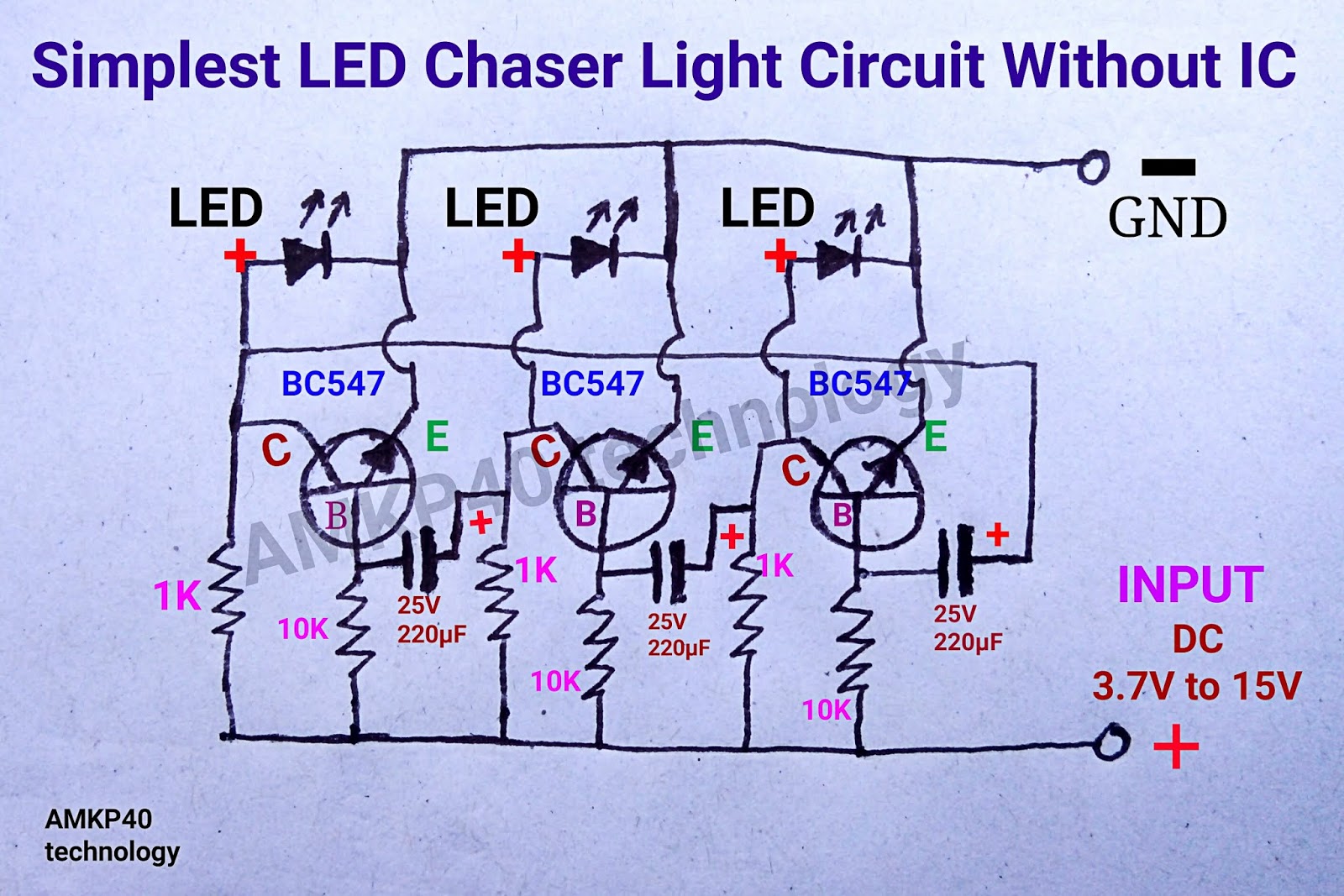
A LED driver circuit is a circuit which can power on and light an LED> We will simply use a transistor and a few resistors to bring about a circuit which, with minimal current, can produce enough current to drive and light an LED.
